Moist - Part 1: The Circuit
Overview
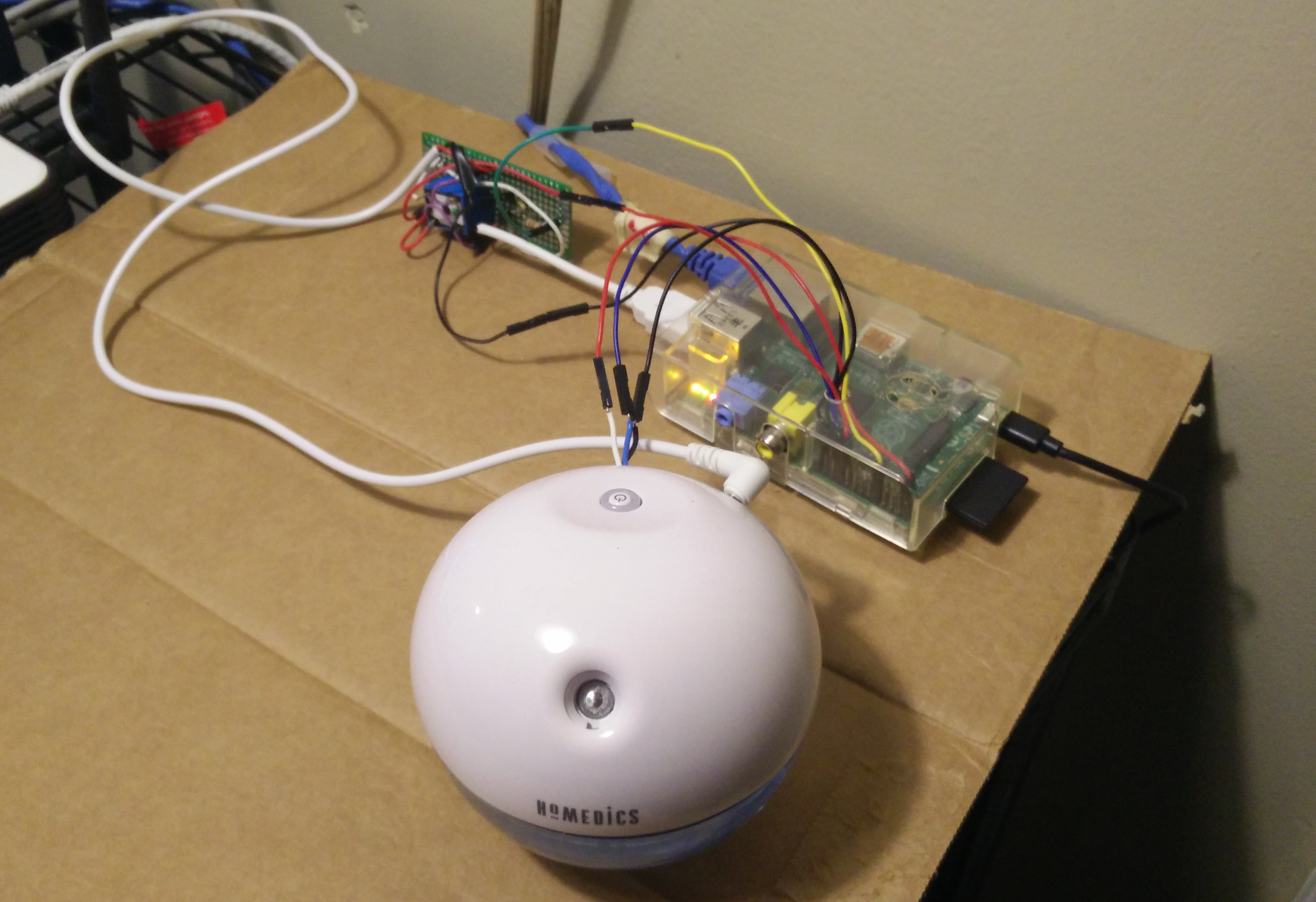
Moist is a USB desk humidifier that is controlled and monitored by a Raspberry Pi Model B. Using the GPIO interface, the Raspberry Pi can turn the power to the humidifier on and off, and also check if the LED is turned on (and what color it currently is). The humidifier has a button on it that stays in the “on” position since control over power is delegated to the circuit. The ring around the button is lit by an LED that can either be blue or red. Blue means the humidifier is on and operating normally. Red means the humidifier has been running too long and should be checked. When the LED is red, moisture stops coming out of the device. This is actually logistically interesting, which I’ll talk about when I get to the software side of things.
A Brief History
The idea came to me while I was visiting my parents over the weekend earlier in the year. My mom was gifted this Homedics Desk Humidifier by a co-worker, and she didn’t know what to do with it. I offered to take it off her hands, and made a joke about connecting it to “the internet of things”. When I found out that there was a hardware hackathon happening at OSU I thought it’d be a great, simple first time project to get into. The idea of connecting something so absolutely useless to the internet amused me to no end, almost as a kind of parody of all the companies pushing IoT without actually thinking about the results1.
This project was originally done with the Raspberry Pi rev 1 Model B, and is currently running on that same Pi. But it wasn’t always. Between the hackathon and my current implementation, I decided to switch to a Raspberry Pi Zero. The Zero doesn’t come with GPIO headers sticking out of it—just holes where you can solder wires to it. If you aren’t experienced with soldering, I highly recommend you don’t go down this route. I ended up spending hours getting everything together, just to break my Zero late in the project by applying too much heat while soldering. If you’re new to this like me, definitely start with a Pi with a header!
Originally, since I lacked a breadboard, I just soldered all my components together. This is a horrible idea. Solder can be brittle and shouldn’t be used for structure, only electrical connectivity. Either use a breadboard, or, when your circuit is done and you want something more stable/smaller, use a prototyping board. This will keep components in place and generally make your circuit easier to keep together.
The Circuitry
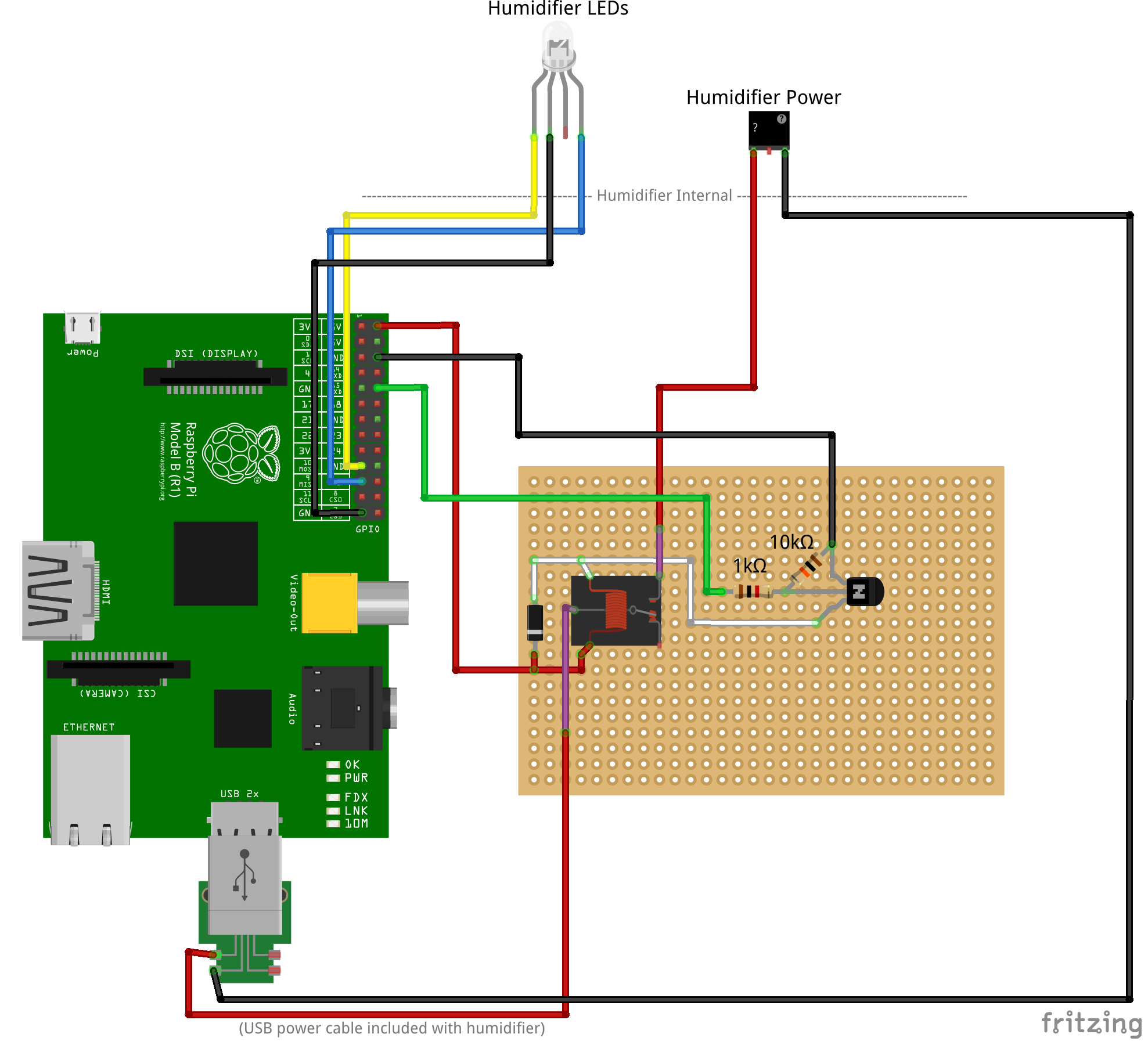
(For a bigger view or to see the source, you can download the Fritzing file).
The best place to start digging into this project is probably the circuits themselves, since they’re really the core of this whole thing. Circuitry is something that I’m definitely not very good at, and pretty much all my knowledge comes from the very basic, simplified circuits in ECE 2000 and 2100. Thankfully, I had a lot of help since I was surrounded by mentors when I first built the prototype. As a side note, if you’re ever on the fence about attending a hackathon or makeathon, you totally should.
There are two major parts to the circuitry: the first part is comprised of two circuits that read the color of the LED. The second part is the circuit that controls power to the humidifier.
Reading the LEDs
This is the part I worked on first, and I had no idea if it would even work. To be honest, I still haven’t yet convinced myself that it should work. This is also the part where a lot of people get confused when I describe the project: most people think of LEDs as output devices, but in this case we want to read them to see if the humidifier has turned them on or off. The Pi never directly turns the LEDs on or off, it only controls power to the whole unit.
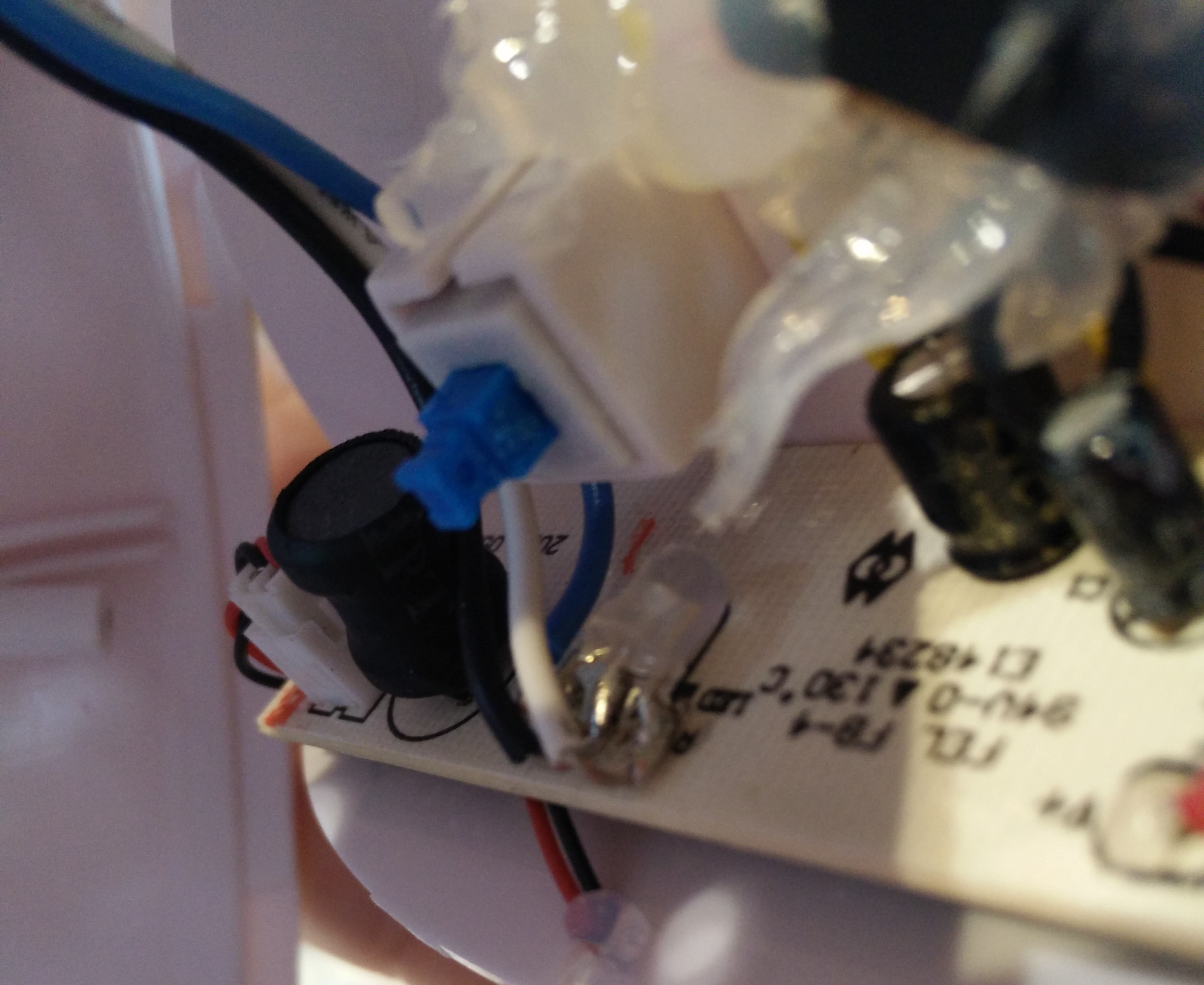
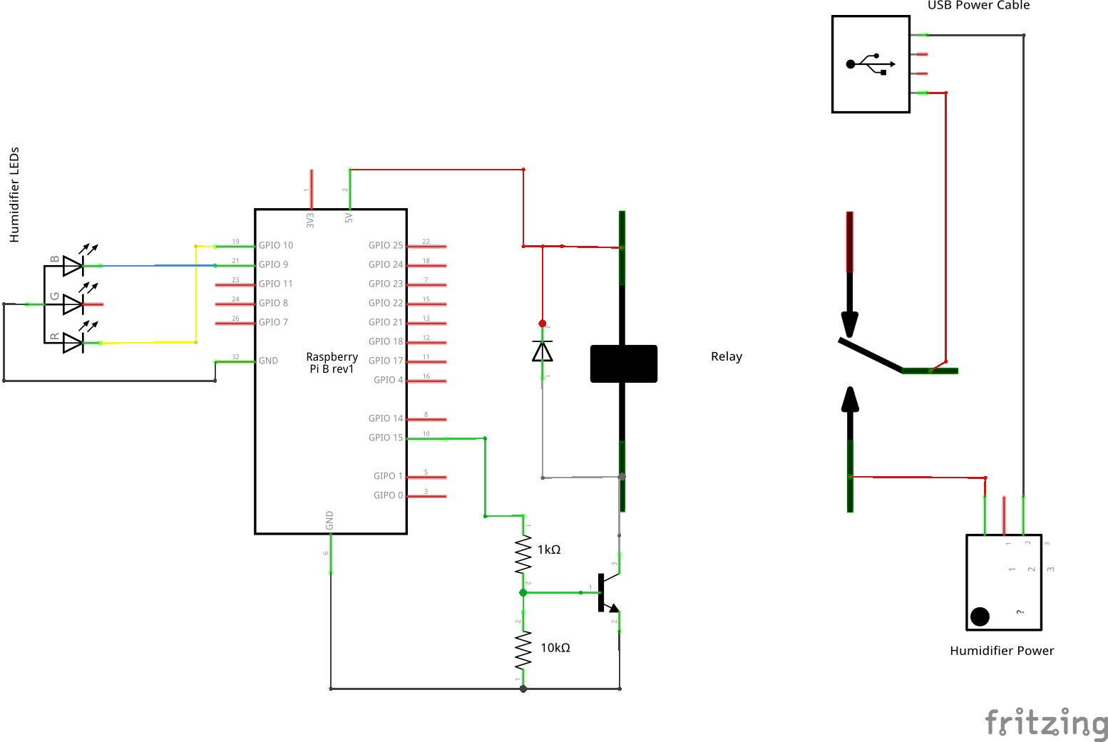
I soldered a wire from the common pin to ground, and a wire from each of color pins to GPIO. In this schematic, that’s pin 9 for blue and pin 10 for red. To actually connect to these wires, I had to drill a small hole in the back of the humidifier casing. It’s just typical plastic and it gave pretty easily without issue.
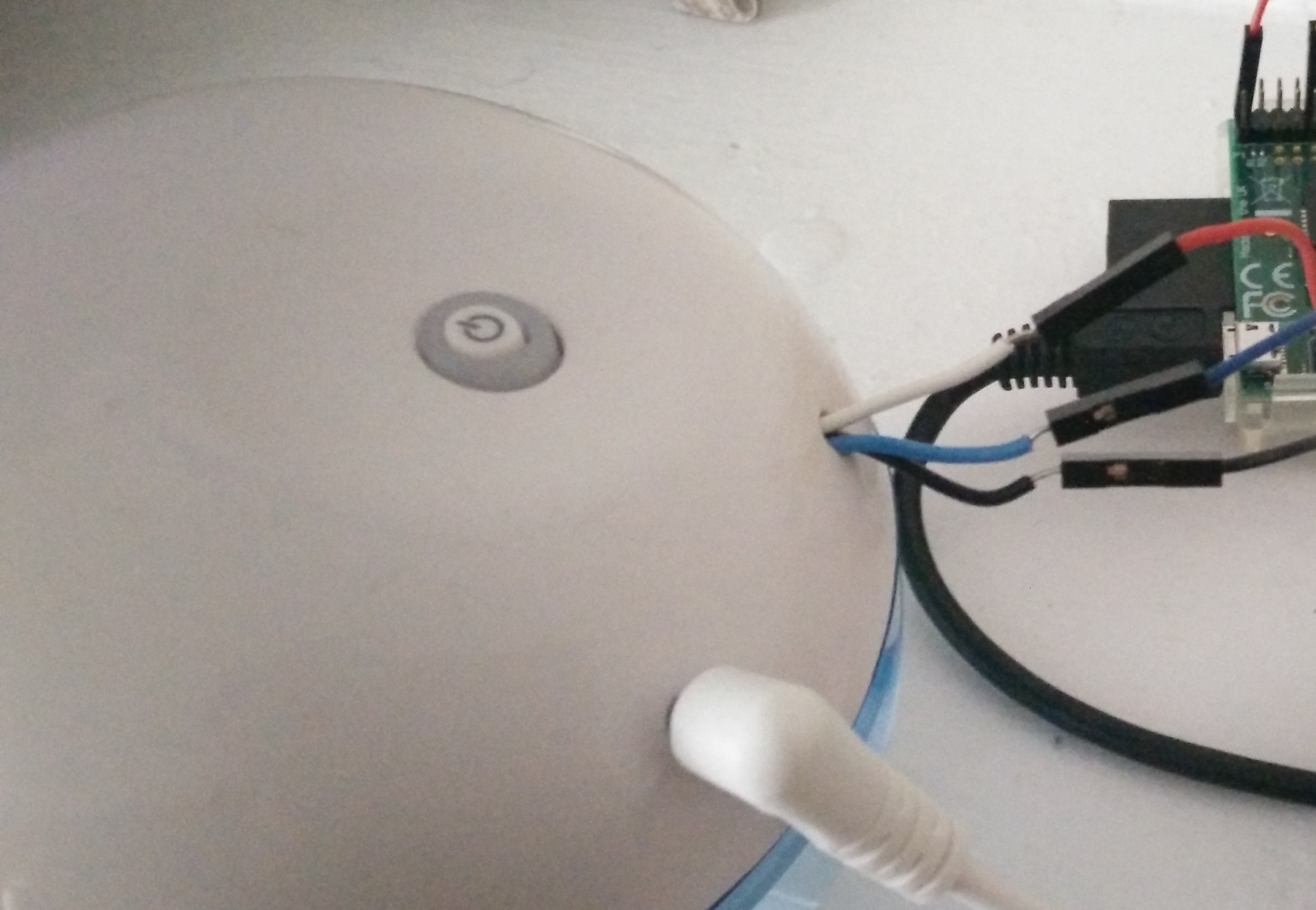
When the either LED turns on, it causes the GPIO pins to be pulled high (to an active 1). I’ll talk about how to read these values later in the server software post.
Controlling the Power
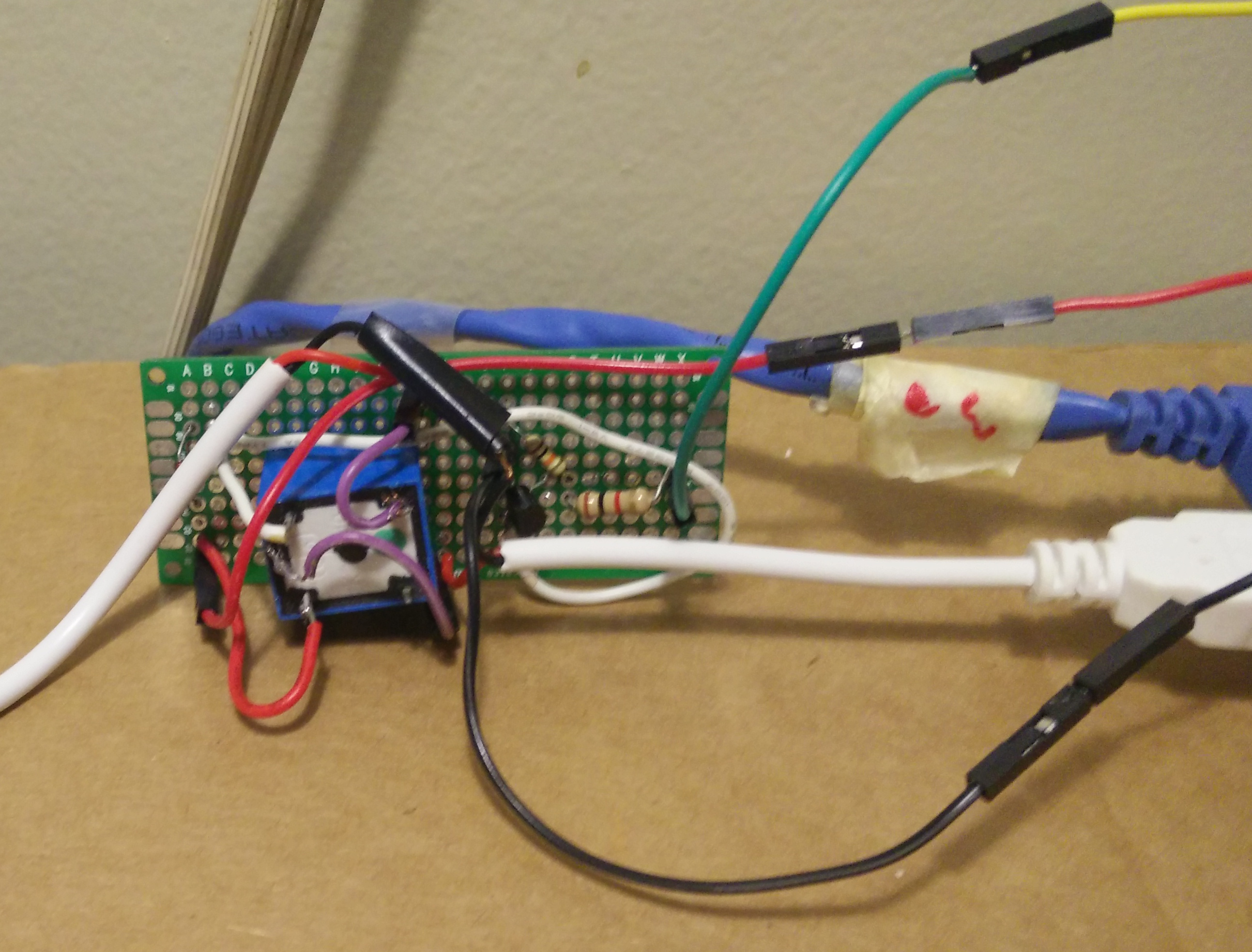
This was the part that I struggled the most with, because it’s much more complex. The goal of this circuit is to use a GPIO pin (in this example, GPIO15) to turn a circuit on and off. One way to accomplish this physically is using a relay. A relay is like a switch: it can turn something on or off by breaking or connecting the circuit. Unlike a normal switch, however, a relay is controlled electronically. When power is applied to the relay, an electromagnet is activated, which physically pulls an arm into place to connect the circuit. This provides an obvious way to control the power: if the GPIO pin is “high” (outputting 3.3v), then the relay turns on, connects the circuit, and the humidifier gains power.
And that was the base of my first attempt at solving this problem: a relay
connected to GPIO 23 and ground, which when activated, would connect the hot
wire of the USB cable, allowing current to flow to the humidifier. It
worked—for about a minute. Then it stopped. I was entirely confused by this. I
thought it might be operator error, but I triple checked the value and output
mode in /sys/. I even hooked up a voltmeter and was getting nothing!
As it turns out, the Raspberry Pi’s GPIO pins have a current limit that’s a bit lower than you might expect, especially compared to some common microcontrollers. According to one source, the Pi is limited to 16mA per pin, and no more than 50mA total. A lot of 5v relays (like the one I used) pull around 70-80mA! I’m lucky that I didn’t burn out my Pi entirely! To this day, a few GPIO pins on my Pi don’t function at all. Always be careful about how much current you draw from the Pi’s GPIO pins!
Thankfully, I still had a few working pins. Now I needed a solution that wouldn’t involve quite so much current through GPIO. As it turns out, the 5v pin is unfused, and will provide you with as much current as the power supply gives to the Pi. So if I could find a way to use that to power the relay, I’d be fine with my 2A power supply, right? But how could I control that circuit? I certainly couldn’t use a relay.
It turns out when I did the research that this kind of thing is actually a well solved problem and that there are a lot of schematics about how to accomplish it (I think you get the idea). These all have a very common structure and an element I’ve never used before: a transistor. Transistors are solid state devices that, among other things, can be used have a much smaller current control a larger one. In this circuit, when the GPIO pin connected to the transistor goes to 3.3v, the current flowing from the top drops to where it won’t power the relay anymore. These circuits also include two interesting properties:
- Most of them use a diode across the relay. This is because when a relay looses power, the stored magnetic energy can sometimes cause current to very briefly flow the other way.
- They use resistors to limit the flow of current through the circuit, since the transistor itself doesn’t provide a lot of resistance. Otherwise, you’d risk burning out your pins just like before
So the circuit I ended up constructing is near identical to the linked ones, using an NPN transistor. With this circuit, the hardware portion of the project was complete2.
In the next post, I’ll describe how the software interfaces with the humidifier using Linux’s GPIO support.
-
If this kind of thing amuses you, be sure to check out the @InternetofShit Twitter ↩
-
Eventually, I’d like to get a water sensor and drop it in the bottom, so I can make sure it stays turned off if there’s no water. It could even email me to go refill it. ↩